Telemetry
About
The Telemetry Module will allow nodes to send a specific message with information from connected sensors. Currently supported sensors are BME280, BME680, DHT11, DHT12, DHT21, DHT22, Dallas 1-wire DS18B20, and MCP9808.
The preferred setup is using I2C, so the telemetry_module_sensor_pin may not be needed.
Usage Notes
For basic usage, start with:
telemetry_module_enabled = 1

telemetry_module_screen_enabled = 1
Depending on which pin your sensor is connected to, set it accordingly:
telemetry_module_sensor_pin = 13
note
The device must be restarted after the settings have been changed for the module to take effect.
Hardware
The sensors can be wired differently, here's one example for sensor DS18B20 https://randomnerdtutorials.com/esp32-ds18b20-temperature-arduino-ide
Example of T-LoraV1 with DHT22 temperature sensor
Setup of a T-LoraV1 with DHT22 temperature sensor.
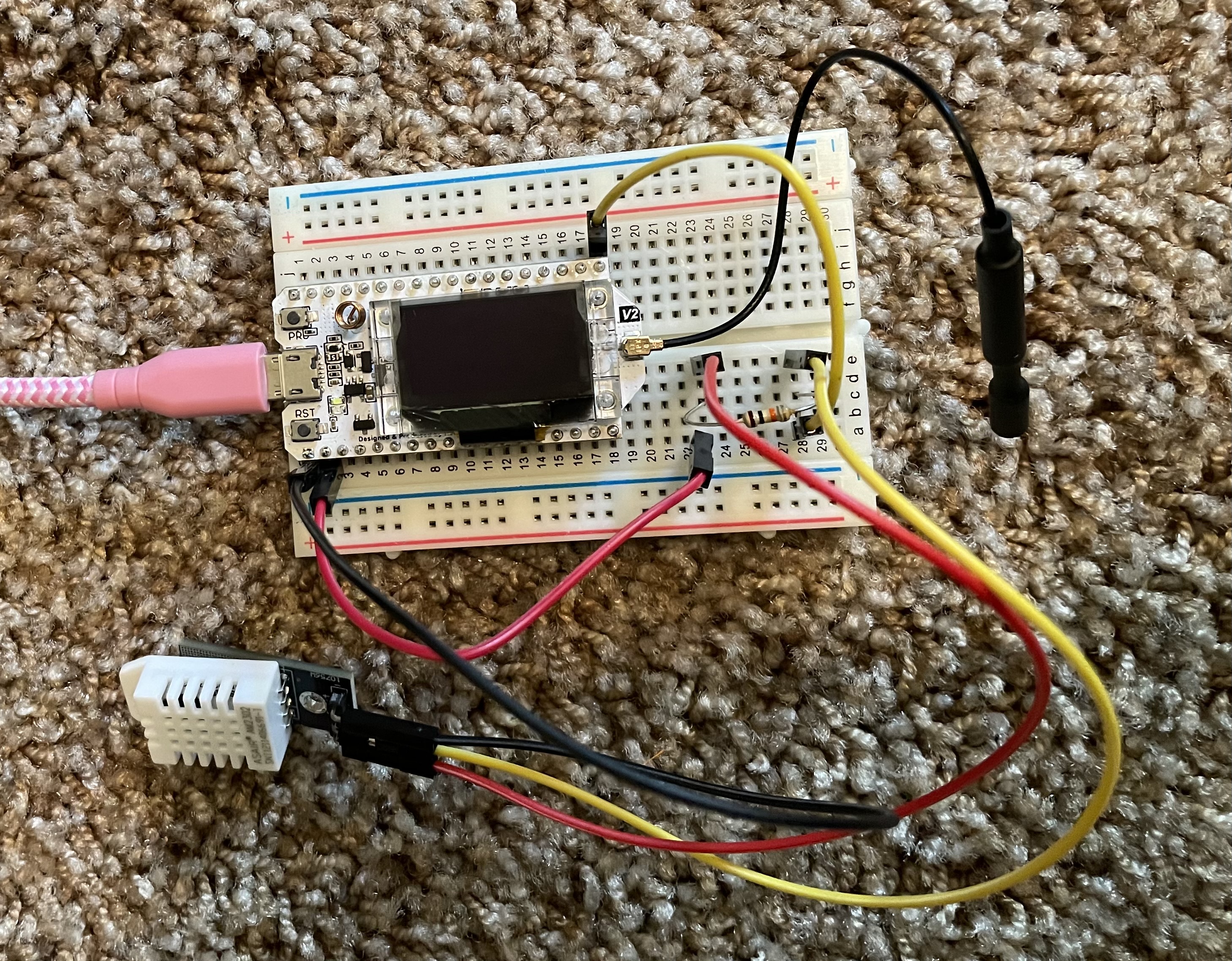
Requirements:
- T-LoraV1 (but any esp32 should work, just be sure to double check which GPIO to use)
- DHT22 sensor
- 10 Kohm resistor (optional, but recommended)
- breadboard (optional)
- two red wires (could be a different color, but 5V is typically red)
- two yellow wires for GPIO (could be a different color)
- one black wire (could be a different color, but GROUND is typically black)
Steps:
- disconnect power/battery
- connect black wire from GROUND to "-" on the DHT22
- connect yellow wire from middle PIN to a row on bread board
- connect red wire from 5V to a row on breadboard
- connect resistor between red and yellow rows
- connect red wire from row with red to "+" on DHT22
- connect yellow wire from yellow row to GPIO on device (ex: GPIO21)
- double check the cabling (if you get it wrong, you can damage the device and/or the DHT22 sensor)
- plug in device
- configure the device:
meshtastic --set telemetry_module_measurement_enabled true --set telemetry_module_screen_enabled true --set telemetry_module_update_interval 15 --set telemetry_module_display_farenheit true --set telemetry_module_sensor_type DHT22 --set telemetry_module_sensor_pin 21
tip
You can change the values above to suit your needs. The commands can be run one at a time or in a group as show above.
- reboot/reset the device (press the RST button or unplug/plug in the device)
- when the device boots it should say "Telemetry" and it may show the sensor data
- if "no data", then triple check the wiring
- if still "no data", run:
meshtastic --info
and verify the the telemetry_module_sensor_type and telemetry_module_sensor_pin
Example of T-LoraV1 with Dallas DS18B20 temperature sensor
Setup of a T-LoraV1 with DS18B20 temperature sensor.
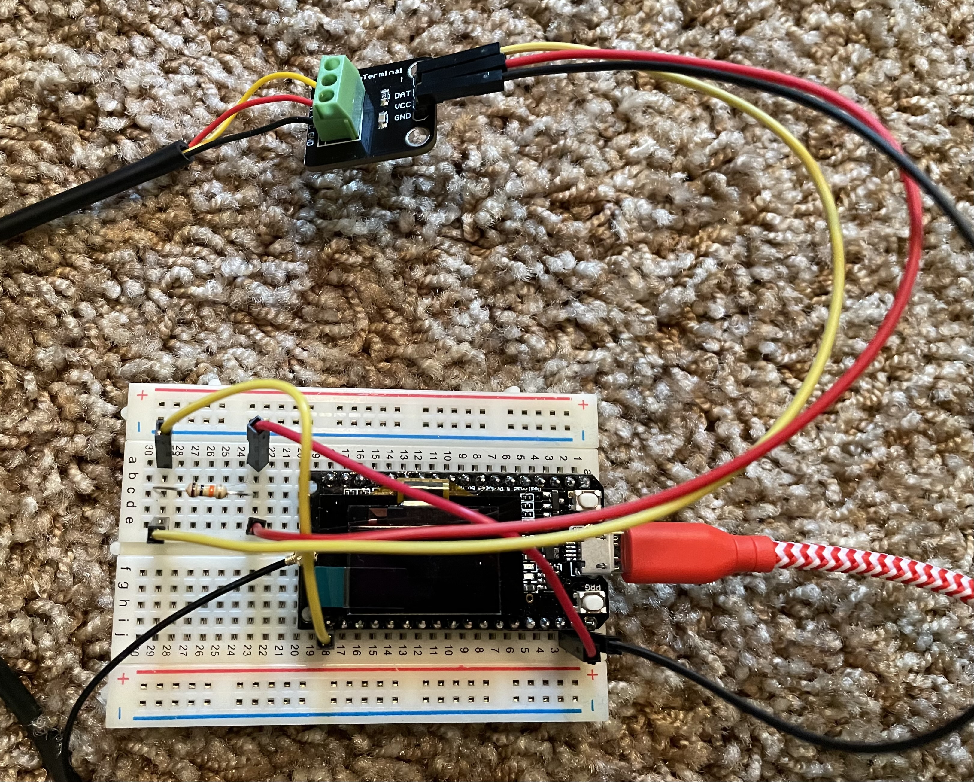
Requirements:
- T-LoraV1 (but any esp32 should work, just be sure to double check which GPIO to use)
- DS18B20 sensor
- 10 Kohm resistor (optional, but recommended)
- breadboard (optional)
- two red wires (could be a different color, but 5V is typically red)
- two yellow wires for GPIO (could be a different color)
- one black wire (could be a different color, but GROUND is typically black)
Steps:
- disconnect power/battery
- connect black wire from GROUND to "-" on the DS18B20
- connect yellow wire from DAT pin to a row on bread board
- connect red wire from 5V to a row on breadboard
- connect resistor between red and yellow rows
- connect red wire from row with red to "VCC" on DS18B20
- connect yellow wire from yellow row to GPIO on device (ex: GPIO21)
- double check the cabling (if you get it wrong, you can damage the device and/or the sensor)
- plug in device
- configure the device:
meshtastic --set telemetry_module_measurement_enabled true --set telemetry_module_screen_enabled true --set telemetry_module_update_interval 15 --set telemetry_module_display_farenheit true --set telemetry_module_sensor_type DS18B20 --set telemetry_module_sensor_pin 21
tip
You can change the values above to suit your needs. The commands can be run one at a time or in a group as show above.
- reboot/reset the device (press the RST button or unplug/plug in the device)
- when the device boots it should say "Telemetry" and it may show the sensor data
- if "no data", then triple check the wiring
- if still "no data", run:
meshtastic --info
and verify the the telemetry_module_sensor_type and telemetry_module_sensor_pin
Example of RAK 4631 with Environment Sensor
Setup of a RAK 4631 with Environment Sensor
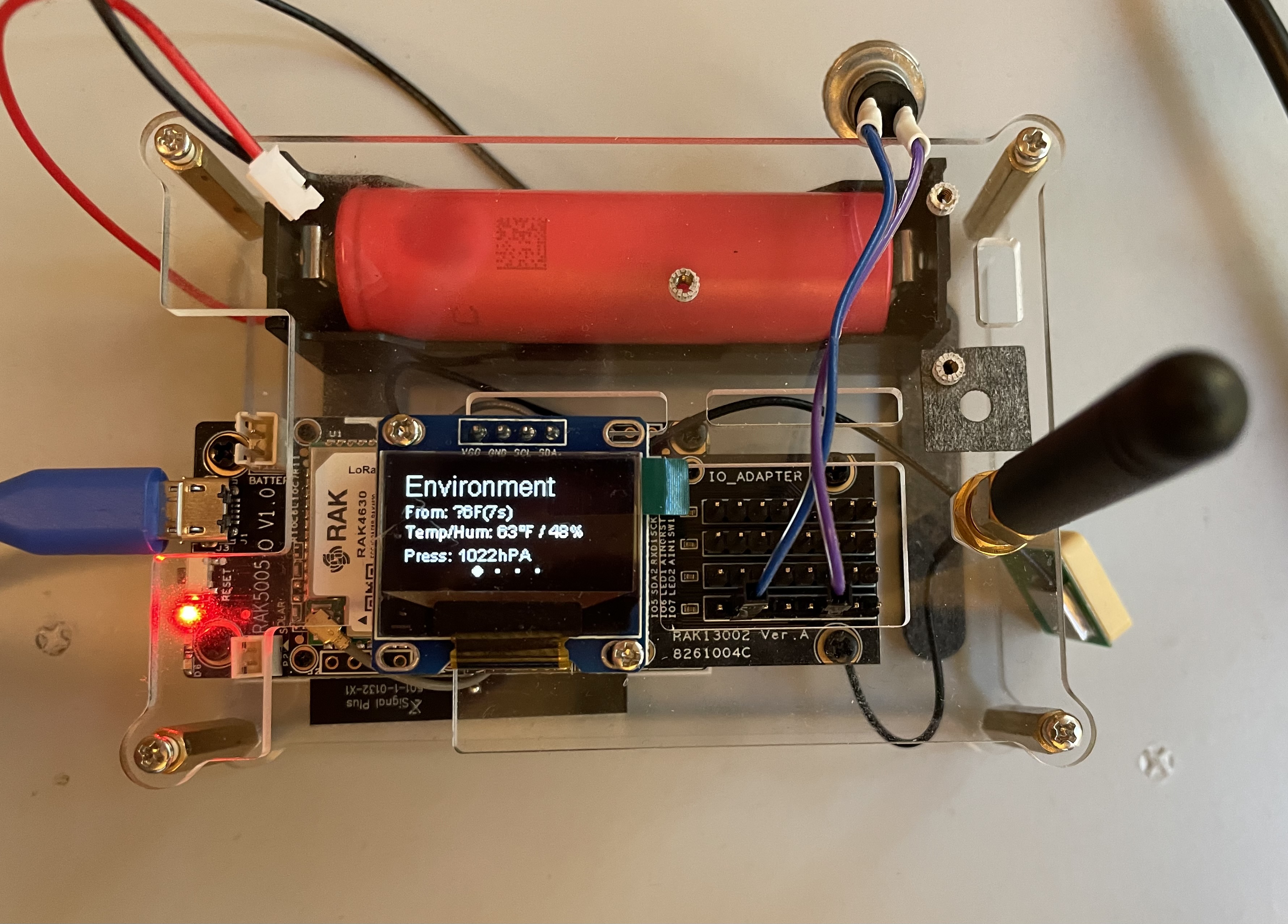
Requirements:
- RAK4631
- Environment Sensor
Steps:
- configure the device:
meshtastic --set telemetry_module_measurement_enabled true --set telemetry_module_screen_enabled true --set telemetry_module_update_interval 15 --set telemetry_module_display_farenheit true --set telemetry_module_sensor_type 6
tip
You can change the values above to suit your needs. The commands can be run one at a time or in a group as show above.
- reboot/reset the device (press the button or unplug/plug in the device)
- when the device boots it should say "Telemetry" and it may show the sensor data
- if still "no data", run:
meshtastic --info
and verify the the telemetry_module_sensor_type
Configuration
Configuration details are available on the Device Settings pages. Configuring the Telemetry Module requires configuring the following modules:
Known Problems
- No default configuration values are currently set, so this must be done when enabling the module.